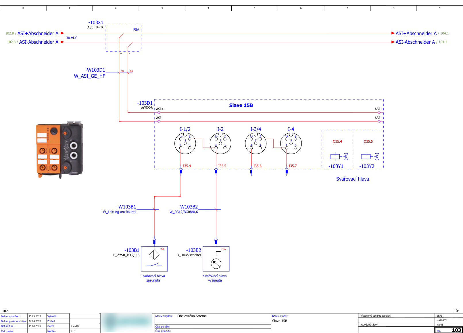
Wiring diagram for cylinder 103A1
MessagesAttached files
Could you also find the wiring diagram for me?
Yes — for 103A1 there are two relevant diagrams (pneumatics + electrical/AS-i):
1) Pneumatic diagram (valve block and cylinder)
The pneumatic sheet shows cylinder 103A1 and its control via the AirBox (-103D1 / AC5228), including 103V1/103V2 and 103S1. Source
2) Electrical diagram (what commands the valves)
The multi-pole electrical diagram shows the wiring of AS-i slave 15B and its outputs:
- outputs Q35.4 / Q35.5 drive -103Y1 / -103Y2 (the valve coils for the welding head), with wiring back to AC5228 (-103D1). Source, Source
If you want, I can also pull up the exact EPLAN page/section where the signals Q103Y1/Q103Y2 are formed in the program (mapped from Automat_DB.Cmd1.Welding_head_fw/rv to the outputs).